Field Tests
Full-Scale Field Test Project Location
Kennesaw State University, Marietta Campus
Green area between Howell Hall and Atrium Building (J)
View Campus Map
Field Test Project Timeline
-
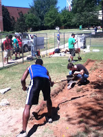
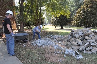
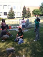
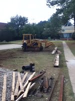
August 18, 2011
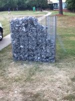
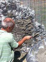
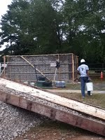
Construction of demonstration wall begins.
Progress:
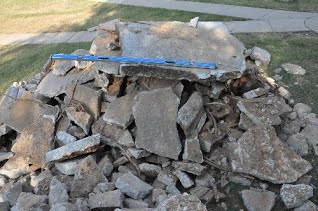
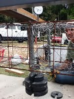
- Wire frame baskets completed
- Donated concrete broken into rubble of varying aggregate size, then dumped into baskets to create wall structure

-
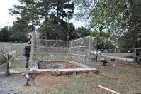
August 19, 2011
Progress:
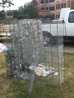
- Demonstration Wall almost completed; still needs some more rubble and cement cover
- Temporary fencing set in place at project site for house construction
-
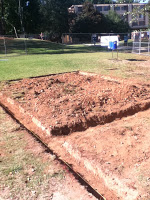
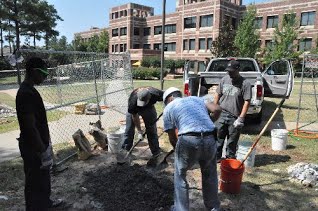
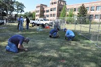
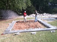
August 23, 2011
Progress:
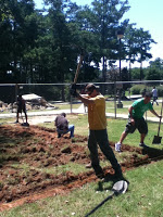
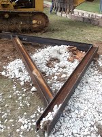
- Foundation has been dug out. Rubble and cement to be filled in tomorrow

-
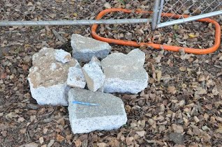
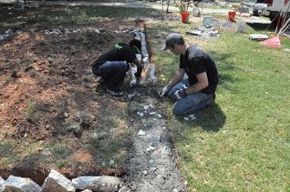
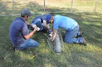
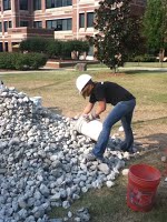
August 24, 2011 and August 25, 2011
Progress:
- Rubble samples collected for performing strength tests
- Foundation formed using rubble and concrete
-
August 26, 2011 - August 27, 2011 and August 29, 2011
Progress:
- Concrete placed to continue forming foundation
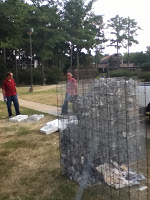
- Rubble Baskets constructed from welded wire mesh and chicken wire netting

-
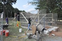
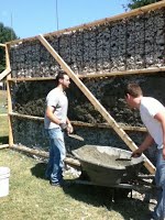
August 30, 2011 and August 31, 2011
Progress:
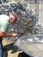
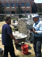
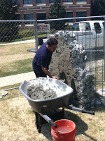
- Cement mixer used to help make concrete, speeding the process to complete foundation
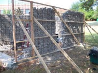
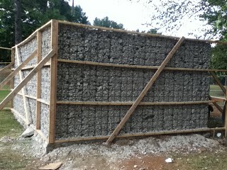
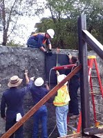
- Baskets for three walls were anchored along foundation with wood framing. Rubble is ready for placement
-
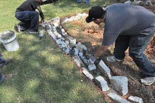
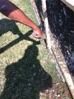
September 1, 2011 and September 2, 2011
Progress:
- Rubble filled into wire baskets for 3 of 4 walls

-
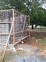
September 7, 2011
Progress:
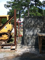
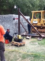
- More rubble brought to site (to fill final wall) along with large I-beams (for testing equipment)
- Basket for final wall secured in place

-
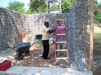
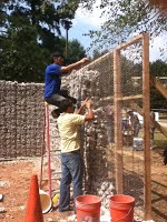
September 8, 2011
Progress:
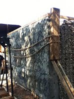
- Rubble filled in all four walls
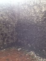
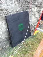
- Placement of concrete finish (stucco) has begun
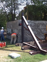
- ATS has begun assembling the loading frame

-
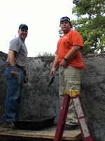
September 12, 2011 - September 17, 2011
Progress:
- Concrete added to cover rubble and mesh on building structure
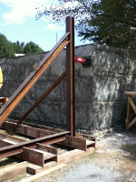
- ATS completes construction of loading frame with hydraulic jack equipment
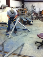
- Parts for displacement frame and gages assembled


-
September 19, 2011
Progress:
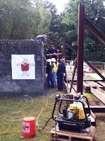
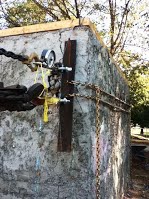
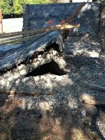
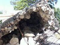
- Wall demolitions were conducted for the public, as demonstrated in the following videos.
- Unreinforced concrete masonry showed extensive brittle failure when hit with the battering ram. The ram was only able to puncture holes in the "rubble wall", causing localized failure on the outer surface
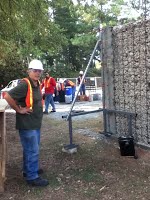
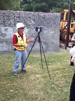
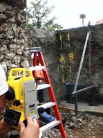
- Initial tests on static loading were conducted. Two hydraulic jacks were fixed to each wall corner. Each was loaded in increments from 100 psi to 790 psi. Displacement/deflection were recorded using: Displacement gage frame (homegrown), Video camera footage, Manual surveying techniques, and 3D point cloud scanner (laser scanning)
-
September 23, 2011
Progress:
- Further static load testing was conducted
- Hydraulic jack placed to apply loads to center of the wall
-
September 28, 2011
Progress:
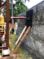
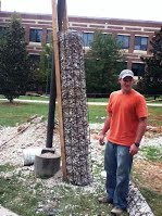
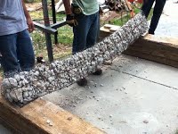
- Triangular rubble column subjected to sag test to measure potential deflection from rubble weight
-
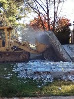
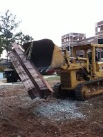
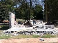
October 7, 2011
Progress:
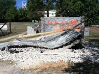
- Rubble house demolition (service provided by ATS)
-
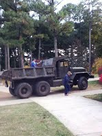
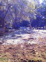
October 27, 2011
Progress:
- Rubble removed from premises (courtesy ATS)